
What this third angle projection lesson covers
- Explain what third angle projection is and where it places each view.
- Project the top and right views of a clevis from its front view.
- Draw the third angle projection symbol and tell it from the first angle one.
- Read a drawing in either convention without mixing them up.
Third angle projection is the convention of drawings made to ASME standards in the United States and Canada. Its rule is easy to remember: each view goes on the side it is seen from. The view from above goes above the front view, and the view from the right goes on its right.
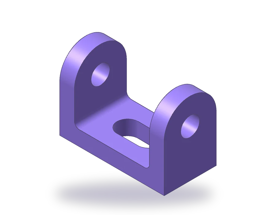
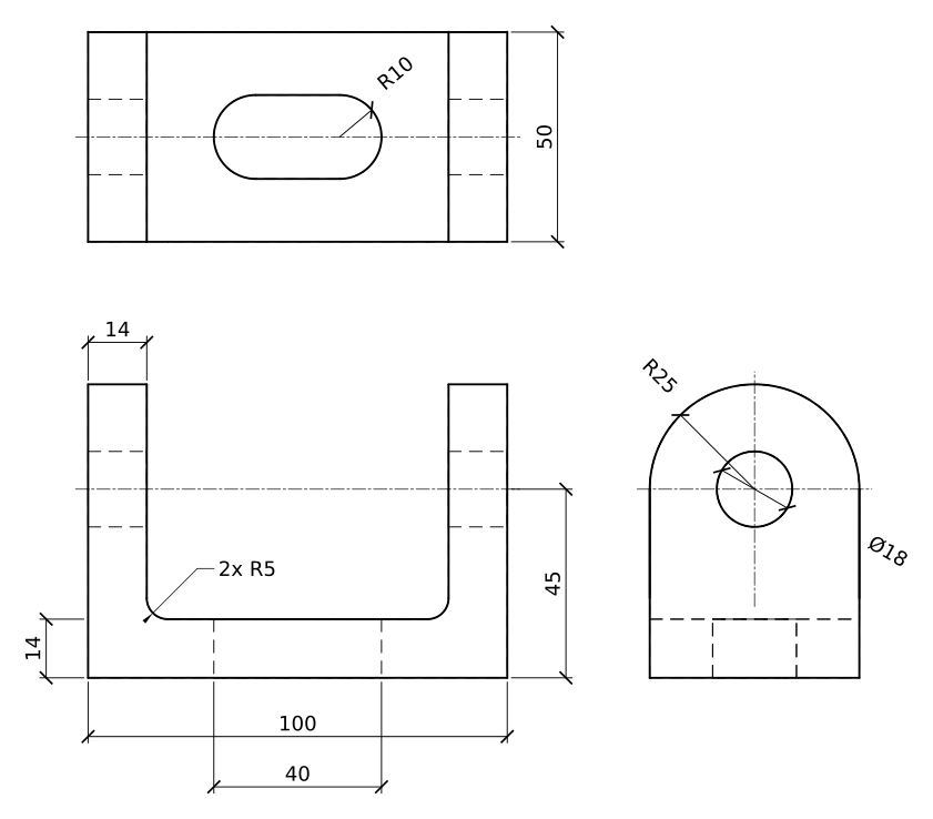
This lesson is drawn in third angle in every language of the site, metric version included, so that both conventions can be practiced. The part is a clevis bracket: a base 100 x 50 x 14 mm with a 40 x 20 slot, and two arms 14 mm thick at its ends, rounded with R25 around a Ø18 hole whose axis is 45 mm above the bottom. R5 fillets join the arms to the base on the inside.
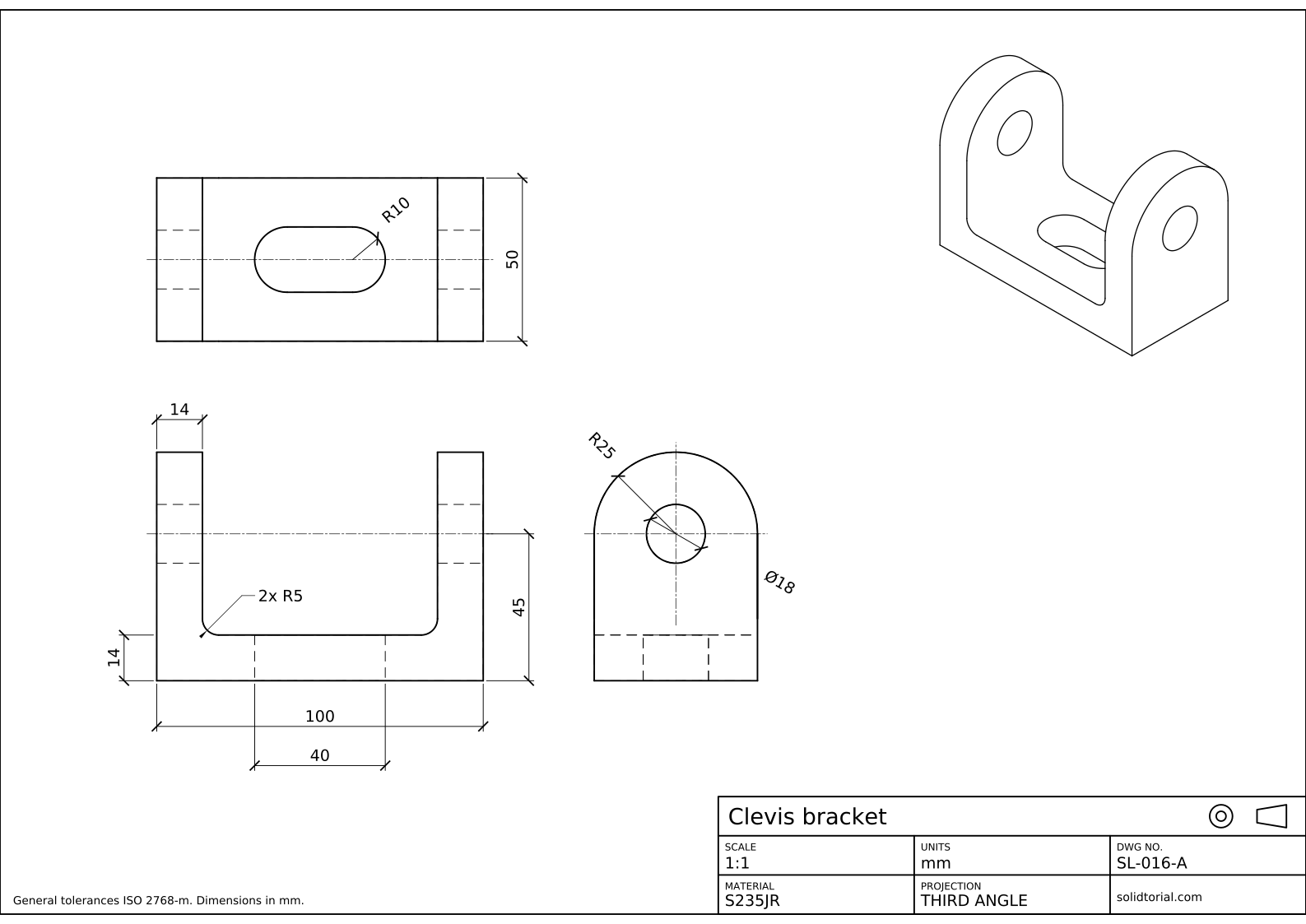
Metric sheet, third-angle projection, scale 1:1 on A3. Click the drawing to open it full size.
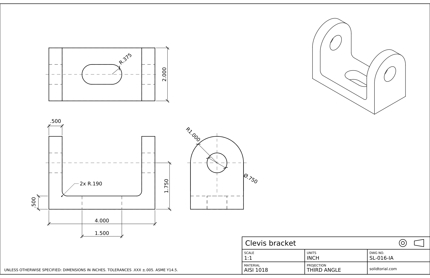
Inch sheet, third-angle projection (ASME), scale 1:1 on ANSI B. Click the drawing to open it full size.
AutoCAD commands for drawing in third angle projection
| Command | Alias | What it does here |
|---|---|---|
RECTANG | REC | Draw the base and the arms in the front view. |
XLINE | XL | Project construction lines up to the top view and across to the right view. |
CIRCLE | C | Draw the R25 top of the arm and the Ø18 hole in the right view. |
FILLET | F | Round the inside corners between arms and base with R5. |
TRIM | TR | Cut the construction lines and the circle back to the outlines. |
Third angle orthographic projection in AutoCAD, step by step
-
Draw the front view of the clevis
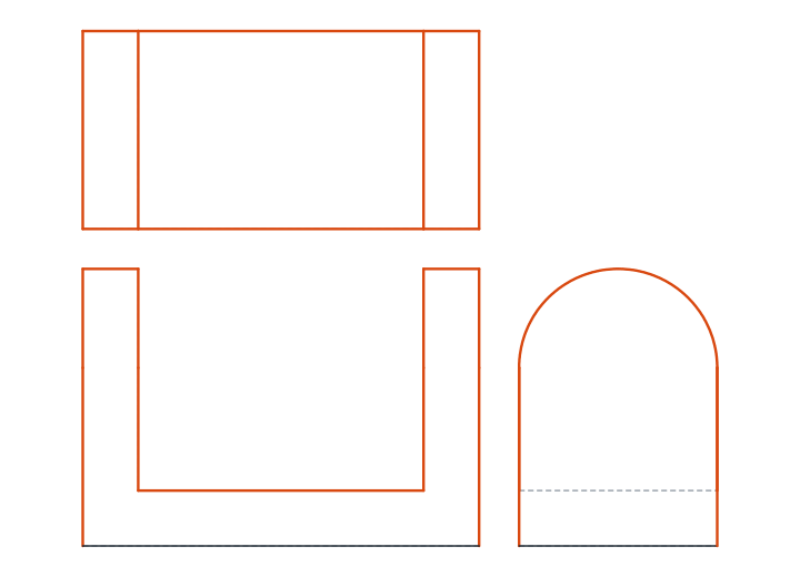
The front view shows the U shape of the clevis. Draw the base, 100 x 14, and the two arms, 14 wide and reaching 70 mm above the bottom: seen from the front, the rounded top of each arm shows only as its highest line. Fillet the two inside corners with
Fand radius 5.The Ø18 hole crosses both arms along the front view, so it appears as two hidden lines 9 mm above and below a center line at 45 mm. The slot in the base is hidden too: two vertical hidden lines 40 mm apart, centered.
-
Place the top view above the front view
In third angle projection the view from above goes above the front view. Project the edges up with
XLand the Ver option and draw the top view, 100 x 50. The arms appear as two strips 14 wide at the ends, with the hole as hidden lines across them. The slot is seen from above at its true shape: 40 long and 20 wide with R10 ends, in the middle of the base.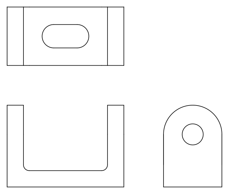
-
Place the right view on the right of the front view
The view from the right goes on the right. Project the heights across with
XLand the Hor option, and take the 50 mm depth from the top view. Here the arm shows its true shape: draw the 50 x 14 base, the sides of the arm up to the 45 mm axis, an R25 arc over the top and the Ø18 hole at its center. The slot is under the arm, so it shows as two hidden lines in the base.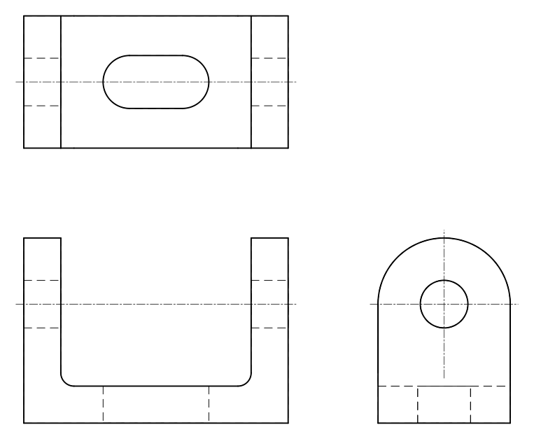
-
Dimension each feature where it is true
Trim the construction lines and add center lines. Then dimension each feature in the view that shows its true shape: in the front view the width 100, the base 14, an arm 14, the axis at 45, the slot length 40 and the fillets as 2x R5; in the top view the depth 50 and the R10 slot ends; in the right view the R25 top and the Ø18 hole.
-
Draw the third angle projection symbol
The symbol is the same truncated cone as in first angle, a trapezoid and two concentric circles, but placed the other way round: in third angle the circles go on the left of the trapezoid, because the view from the left would be drawn on the left. Put it in the projection field of the title block. Compare it with the symbol of the T-slot block in the first angle projection lesson.
Third angle projection example to practice: a larger clevis
Draw a larger clevis in third angle on your own: a base 120 x 60 x 16 with a 50 x 24 slot, arms 16 thick rounded with R30 around a Ø22 hole whose axis is 54 mm above the bottom, and R6 fillets inside. Place the top view above and the right view on the right, and add the third angle symbol.
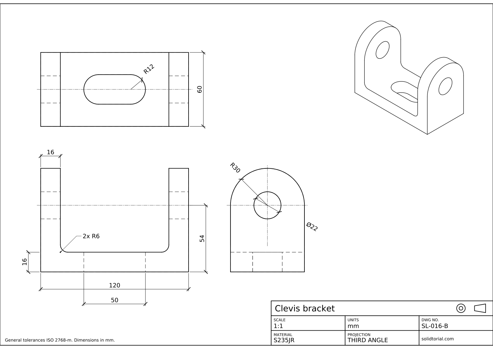
Metric sheet, third-angle projection, scale 1:1 on A3. Click the drawing to open it full size.
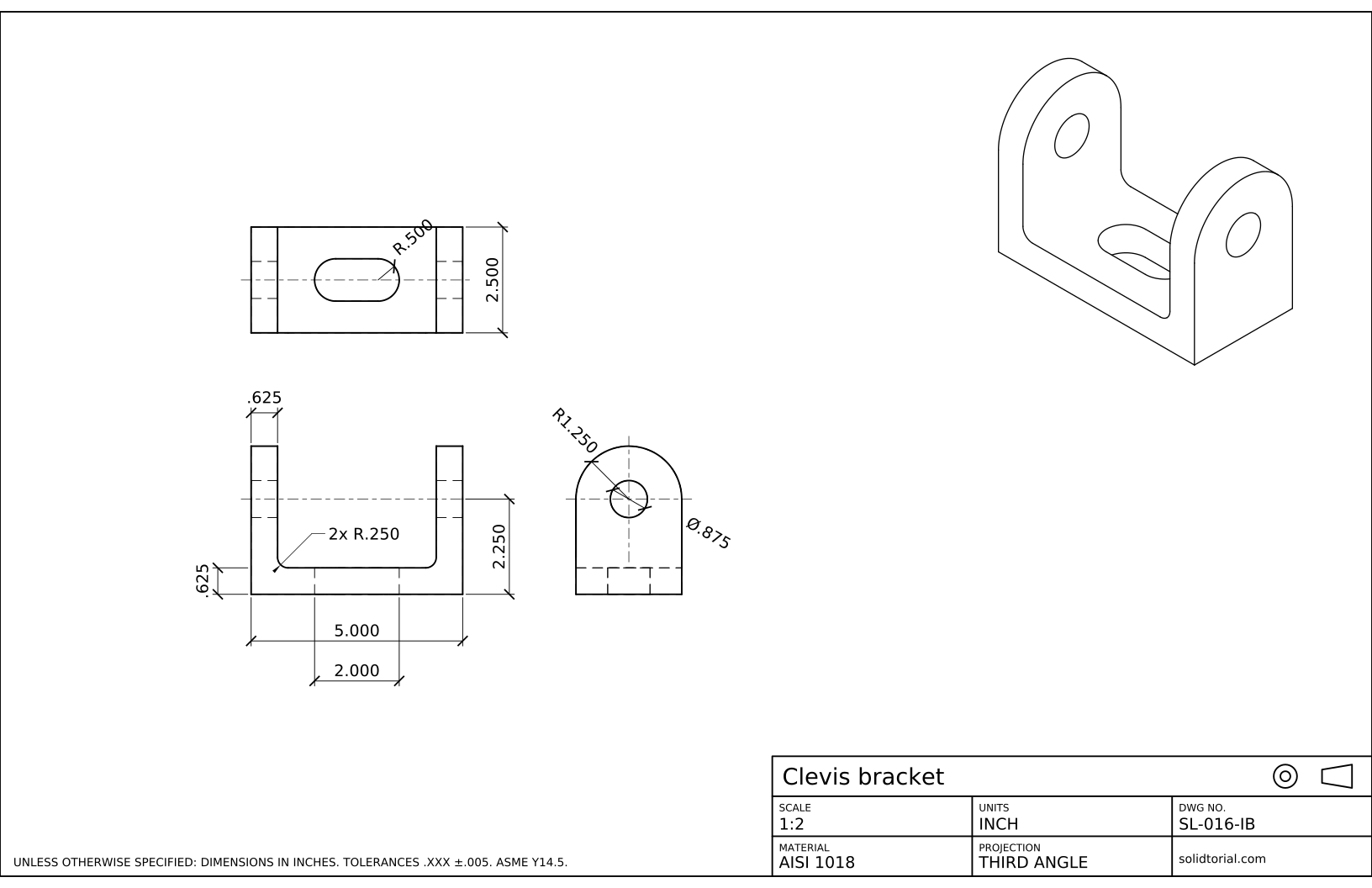
Inch sheet, third-angle projection (ASME), scale 1:2 on ANSI B. Click the drawing to open it full size.
Show the solution files
Metric sheet, third-angle projection, scale 1:1 on A3. Click the drawing to open it full size.
Inch sheet, third-angle projection (ASME), scale 1:2 on ANSI B. Click the drawing to open it full size.
Common third angle projection mistakes
- Top view below the front view. That is first angle. In third angle the view from above goes above.
- Drawing the left view on the right. In third angle the view on the right is the view from the right.
- Mixing conventions on one sheet. All the views of a drawing follow the convention stated by its symbol.
- Dimensioning the hole in the front view. There it is a pair of hidden lines. Its diameter goes in the right view, where it is a circle.
- Copying the symbol from a first angle template. The circles end up on the wrong side. Check the symbol whenever you change templates.
What is third angle projection
Imagine the part in the third quadrant formed by a vertical and a horizontal plane, behind transparent planes that stand between you and the part. Each view is traced on the plane in front of it, and when the planes are unfolded, each view stays on the side it was seen from. The view from below goes below the front view, the view from the left on its left, and the view from behind at the end of the row.
First angle vs third angle projection
Both conventions use the same views; only their positions change.
| First angle | Third angle | |
|---|---|---|
| View from above | Below the front view | Above the front view |
| View from the left | On the right of the front view | On the left of the front view |
| View from the right | On the left of the front view | On the right of the front view |
| Symbol | Circles on the right of the cone | Circles on the left of the cone |
| Where it is used | ISO drawings: Europe, India and most of the world | ASME drawings: United States and Canada |
A drawing without its symbol can be read wrongly: a part drawn in one convention and read in the other comes out mirrored. That is why the symbol belongs in every title block.
Third angle projection symbol
The symbol is drawn with simple proportions: the trapezoid of the cone and its two circles, with the small circle matching the narrow end of the cone. On every sheet of this site it sits at the right end of the title row of the title block, and the projection field below repeats the convention in words.
Third angle projection questions
What is third angle projection?
An orthographic projection in which each view is placed on the side it is seen from: the top view above the front view, the right view on its right. It is the convention of ASME drawings.
What is the difference between first and third angle projection?
The views are the same, but their positions are swapped: in first angle the top view goes below the front view and the left view on its right; in third angle the top view goes above and the right view on the right.
Which countries use third angle projection?
Mainly the United States and Canada, following ASME standards. Most other countries use first angle projection, the ISO convention, although companies that work with American customers often use third angle too.
How do I know if a drawing is in third angle?
Look for the symbol in the title block: circles on the left of the cone mean third angle. Without a symbol, a top view above the front view points to third angle.
Updated: September 26, 2026